

Description
SUPERTECH PREMIUM MACHINING COMPONENTS
Technical Specification Data Sheet — Solid Dead Centers
Product Overview & Key Characteristics
- Material Composition: Manufactured from premium high-carbon alloy tool steel to ensure structural integrity under demanding production conditions.
- Geometric Precision: Engineered to maximize surface area contact, delivering superior roundness and finish consistency during turning and grinding cycles.
- Material Hardness: Heat-treated up to 60 HRC (Rockwell C Scale) across critical wear zones, offering advanced defense against premature breakdown.
- Concentricity Accuracy: Meticulously ground tolerances guaranteeing concentricity deviation remains within 0.005mm T.I.R. (Total Indicator Reading).
Dimensional Specification Table
| Model No. (Morse Taper) |
D (Gauge Dia. mm) |
A (Point Lgth. mm) |
C (Body Lgth. mm) |
L (Total Lgth. mm) |
(θ)Angle
|
| STDC2 (MT2) | 19 | 31 | 69 | 100 | 60° |
| STDC3 (MT3) | 25 | 39 | 86 | 125 | 60° |
| STDC4 (MT4) | 32 | 47 | 108 | 155 | 60° |
| STDC5 (MT5) | 46 | 64 | 136 | 200 | 60° |
| STDC6 (MT6) | 64 | 84 | 186 | 270 | 60° |
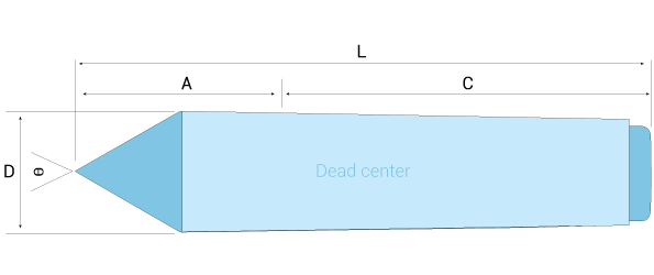
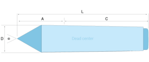
Schematic Diagram & Dimensional Reference Nomenclature
Use the standard industrial descriptions below to reference parameters mapped in the component drawing:
- D (Gauge Diameter): Mapped to the maximum outer diameter profile parameter cross-section of the taper body at the defined gauge boundary line.
- A (Point Length): Represents the operational geometric projection extending outward from the taper’s gauge boundary to the vertex point.
- C (Body Length): Details the entire insertion profile depth dimension of the solid Morse Taper shank body.
- L (Overall Length): Reflects the exact global engineering end-to-end master length calculation value (Formula: L = A + C).
- Angle (θ – Theta): Indicates the global standard 60-degree precision ground workpiece mating center point geometry angle.
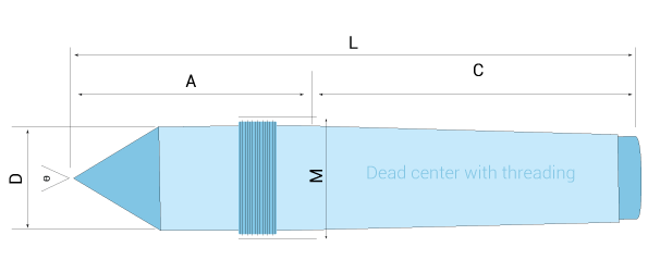
Threaded Dead Center Dimensional Matrix
| Model No. | D
(Gauge Dia. mm) |
A
(Point Lgth. mm) |
C
(Body Lgth.mm) |
L
(Total Lgth.mm) |
(θ)
Angle |
M
(Thread Spec) |
| STDCT2 (MT2) | 18 | 48 | 69 | 117 | 60° | M 22×1.5 |
| STDCT3 (MT3) | 24.1 | 57 | 86 | 143 | 60° | M 27×1.5 |
| STDCT4 (MT4) | 31.6 | 72 | 108 | 180 | 60° | M 36×1.5 |
| STDCT5 (MT5) | 44.7 | 87 | 136 | 223 | 60° | M 48×1.5 |
| STDCT6 (MT6) | 63.8 | 108 | 186 | 294 | 60° | M 68×1.5 |
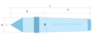
Engineering Blueprint Nomenclature Map
D : Gauge Diameter — The maximum outer diameter of the taper body ground at the primary gauge reference line.
A : Point Length — The protruding extension length running from the main gauge line line out to the sharp tip of the center.
C : Body Length — The total standard length of the structural tapered shank matching machine spindle configurations.
L : Overall Length — The total end-to-end dimension of the threaded dead center layout framework (A + C).
θ : Included Angle — The standard ground 60-degree point cone profile matching standardized workpieces.
M : Thread Specification — Precision metric coarse/fine thread sizing configuration for custom extraction mechanics.


